
EUROPE PARTS · WATER RECYCLING SYSTEMS
Water recycling for aggregate washing.
A complete circuit, from raw water to reuse.
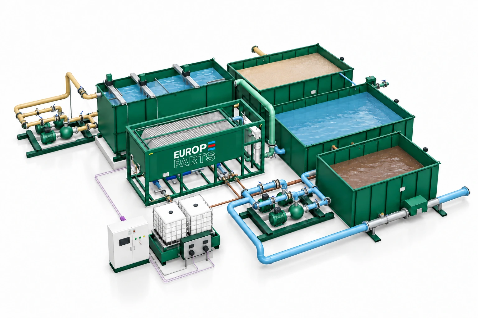
Europe Parts WRS systems connect equalisation, reaction and flocculation, lamella clarification, tanks, return pumping and sludge handling. Compare four system families and choose a layout around your water, solids and available space.
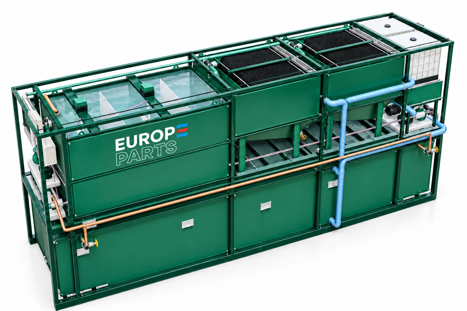
Return water to the process. Give solids their own route.
Reliable water recovery depends on more than a clarifier. Feed variation, conditioning, storage, pumping and sludge removal must work as one process.
Raw-water storage absorbs variation from aggregate washing before treatment.
Reagents and mixing conditions are selected from representative water tests.
Settleable flocs are separated from the clarified water stream.
Stored process water is pumped back to the washing circuit with controlled make-up water.
The water circuit
Collect, condition, clarify, store and return. Operating levels and pump duty are coordinated with the washing plant. Make-up water covers the measured losses and operating requirement.
The solids circuit
Concentrated sludge is collected in dedicated storage or compartments. Buffer volume, drainage, removal frequency and any downstream dewatering are selected from the actual solids load.
Compare the WRS family.
Start with flow, then validate the selection against water samples and the solids balance. WRS 25, 50 and 100 offer standard and M layouts; WRS 150 uses separate tanks.
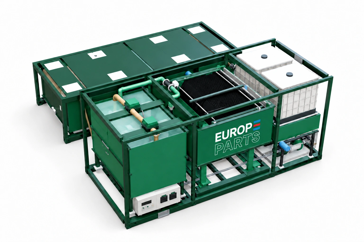
25 m³/h treatment basis
WRS 25
A compact circuit for lower-flow washing applications.
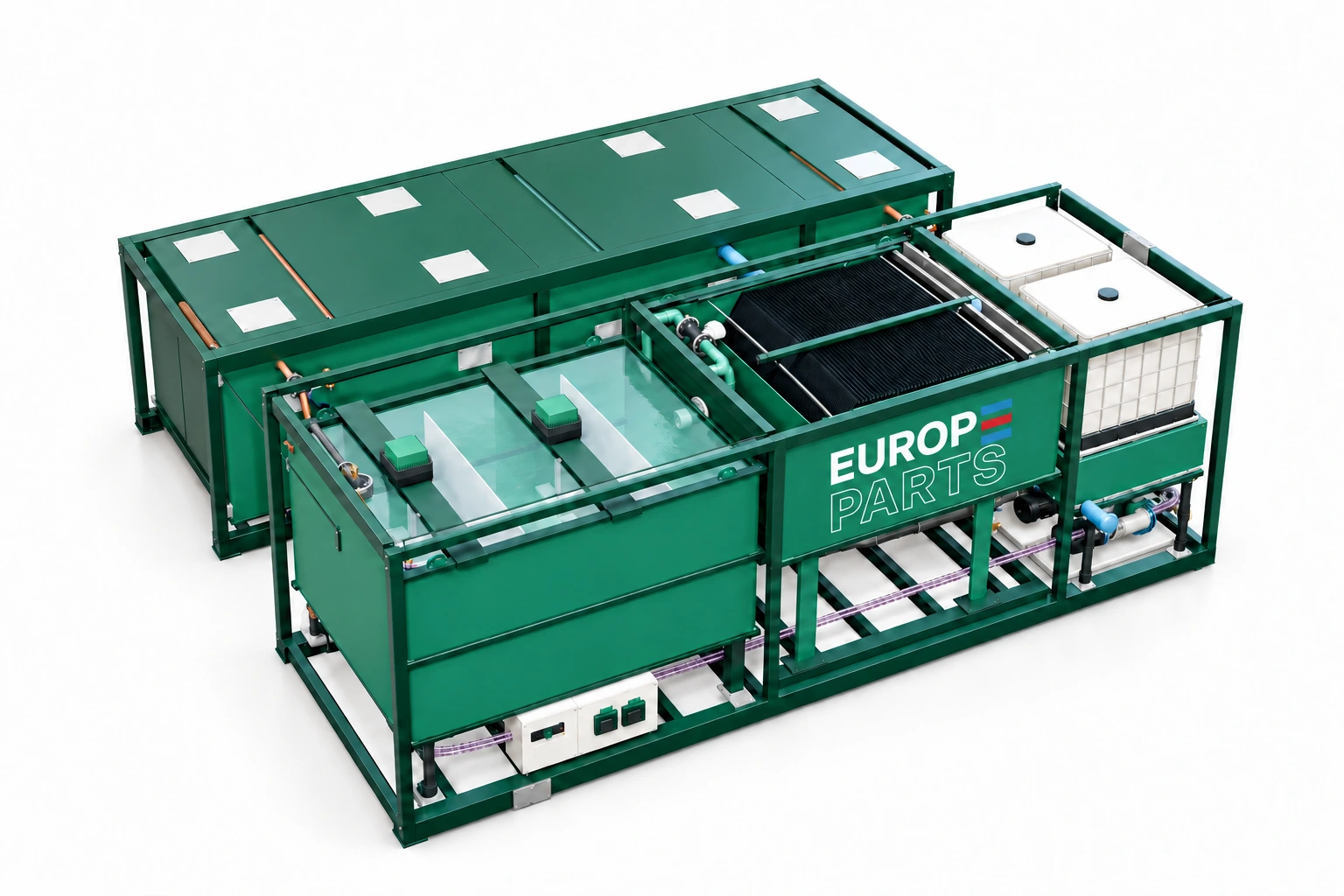
50 m³/h treatment basis
WRS 50
A coordinated treatment circuit for a 50 m³/h hydraulic basis.
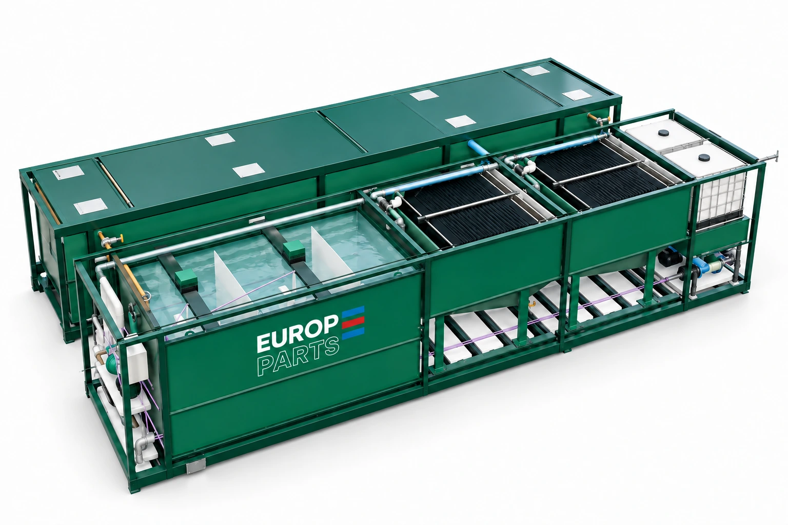
100 m³/h treatment basis
WRS 100
Two clarification branches. One coordinated water circuit.
120 m³/h treatment basis
WRS 150
Water recovery for a 150 m³/h washing circuit.
| Family | Hydraulic reference | Lamella units | Reaction volume |
|---|---|---|---|
| WRS 25 / 25M | 25 m³/h | 1 | 5 m³ |
| WRS 50 / 50M | 50 m³/h | 1 | 10 m³ |
| WRS 100 / 100M | 100 m³/h | 2 × 50 m³/h | 20 m³ |
| WRS 150 | 120 m³/h treatment; 150 m³/h washing circuit | 1 | 30 m³ |
Hydraulic flow is not the same as net recovered water. Reagent preparation water, recirculated streams and losses in aggregates and sludge all enter the water balance. No universal recovery percentage is assumed.
Two ways to organise your installation.
Separate tanks
Treatment equipment sits alongside the storage module, allowing access around each unit and flexible pipe routing. Existing tanks can be assessed for integration after checking useful volume, condition and levels.
Modular M configuration
For WRS 25M, 50M and 100M, the treatment frame is positioned above the tank module. This organises the equipment vertically while retaining the same hydraulic selection basis.
| Family | Separate tanks | M layout |
|---|---|---|
| WRS 25 | 10 × 10 m | 10 × 8 m |
| WRS 50 | 12 × 10 m | 12 × 8 m |
| WRS 100 | 16 × 10 m | 16 × 8 m |
| WRS 150 | 22 × 16 m | Separate-tank layout |
These are indicative planning areas, not shipping dimensions. Final access, foundations, loads and pipework are confirmed in the layout drawing.
Specify the complete duty.
Send the average and peak wash-water flow, operating hours, material type, fines and clay content, a representative water sample and a site plan. Include the available route for sludge disposal or further dewatering.
The proposal defines equipment, controls, civil works, assembly and connections. A filter press or dry sludge cake production is not implicitly included.
Frequently asked questions
Can the system use existing ponds or tanks?
Integration is assessed against useful volume, watertightness, pipe levels, cleaning access and the plant operating cycle.
Is the model number a guaranteed recovery rate?
The numbers identify reference system families. The actual operating flow and recovered-water volume depend on the water and solids balance, settling tests and selected equipment.
EUROPE PARTS · APPLICATION ENGINEERING
Build the right configuration for your site.
Tell us about your water recycling requirement, the material, operating flow and available space. Our team will prepare the equipment selection, layout and scope of supply.
EUROPE PARTS · DALMAN INTERMEDIERE SRL · Bucharest, Romania