
EUROPE PARTS · WATER RECYCLING SYSTEMS
WRS 100
Water recycling system
Two clarification branches. One coordinated water circuit.
WRS 100 combines a 20 m³ reaction volume with two parallel lamella units, each with a reference hydraulic limit of 50 m³/h. Clarified water is collected for reuse while concentrated sludge follows a separate route.
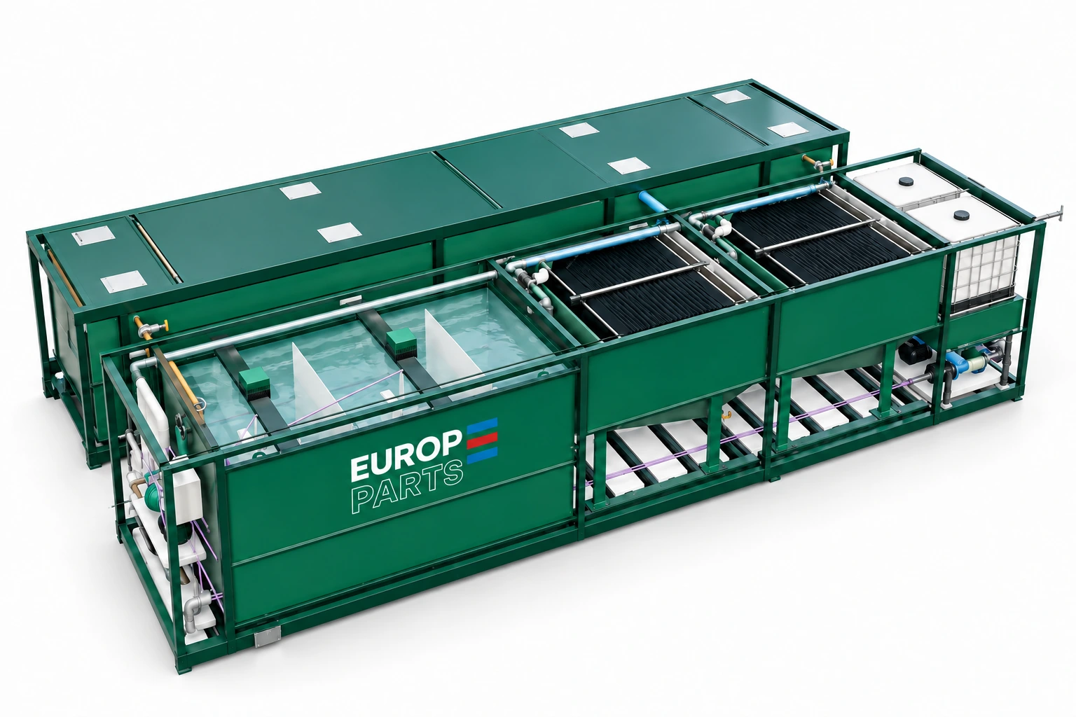
Where WRS 100 fits.
Feed equalisation, flocculation and clarified-water return are coordinated with the washing plant. Sludge removal must keep pace with the separated solids. A low average water flow may still contain significant peaks, so buffer storage is part of the selection. Two branches allow the plant to be organised around common feed and controlled sludge discharge. Operating one branch requires reduced flow; the remaining branch does not automatically absorb the capacity of the stopped unit.
Reference configuration.
| Parameter | Reference configuration |
|---|---|
| Model | WRS 100 / WRS 100M |
| Hydraulic treatment limit | 100 m³/h |
| Useful reaction volume | 20 m³ |
| Lamella clarification | 2 × 50 m³/h in parallel |
| Reagent preparation | Two IBC reagent storage positions, dosing and polymer preparation; selection after water tests |
| Storage | Separate raw-water, clarified-water and sludge circuits |
| Indicative area — separate tanks | 16 × 10 m |
| Indicative area — M layout | 16 × 8 m |
Planning areas are not transport dimensions. Operating flow is confirmed through settling tests, the solids balance and pump checks. High clay loads can require a lower throughput or a different configuration.
WRS 100 or WRS 100M?
WRS 100 · separate tanks
Tanks are positioned beside the treatment frame. The indicative planning area is 16 × 10 m. Pipe routing and service access determine the final arrangement.
WRS 100M · modular arrangement
The treatment equipment is positioned above the tank module. The indicative planning area is 16 × 8 m. The same hydraulic basis is retained in a more vertically organised layout.
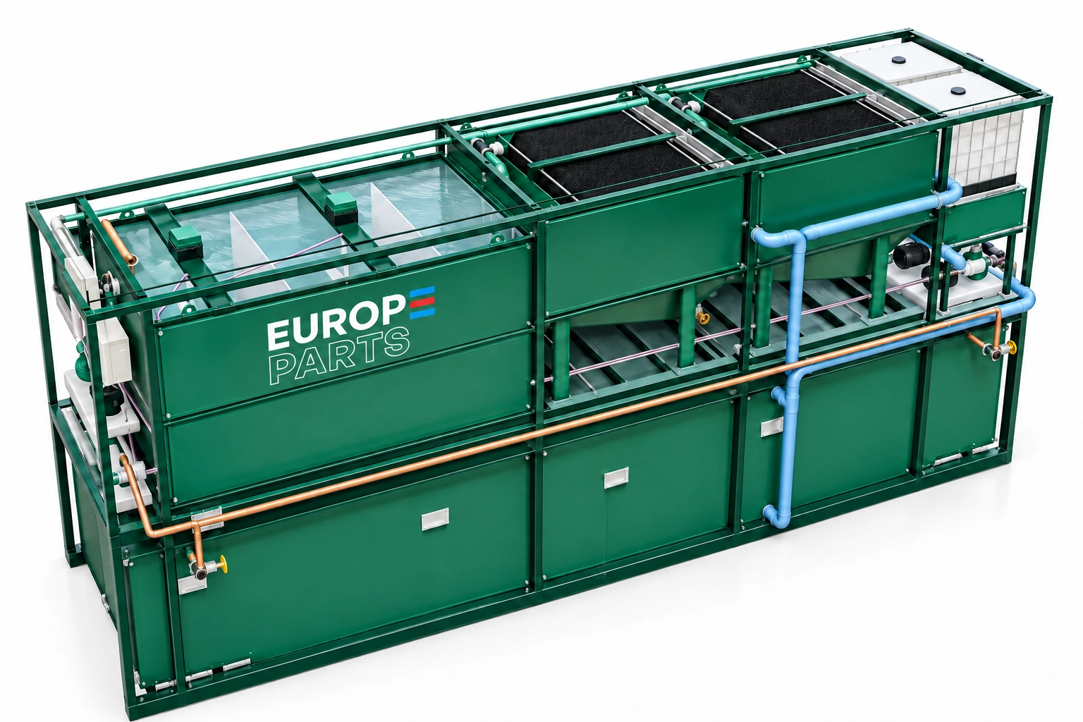
A system built around the whole circuit.
Treatment & return
- Reaction and flocculation tank.
- Lamella clarification appropriate to the model.
- Polymer preparation and reagent dosing.
- Clarified-water storage and return pumping.
Operation & integration
- Raw-water collection and sludge management.
- Level monitoring and operating conditions.
- Pipe routes coordinated with the site.
- Cleaning and maintenance access.
The commercial proposal confirms the exact equipment, controls, civil works, assembly and connections included. Storage volumes and sludge-removal frequency depend on solids loading and operating hours.
Frequently asked questions
Is 100 m³/h guaranteed for every wash water?
This is the reference hydraulic limit. Admissible operating flow depends on solids concentration, clay characteristics, flocculation, pumping and sludge removal. Representative tests confirm selection.
What information is needed for a proposal?
Provide average and peak flow, working hours, representative water samples, material type, a site plan and the available route for sludge removal.
EUROPE PARTS · APPLICATION ENGINEERING
Build the right configuration for your site.
Tell us about your WRS 100 requirement, the material, operating flow and available space. Our team will prepare the equipment selection, layout and scope of supply.
EUROPE PARTS · DALMAN INTERMEDIERE SRL · Bucharest, Romania