
EUROPE PARTS · TECHNICAL CATALOGUE
Crusher Chamber Liners
Replaceable impact aprons, breaker plates and chamber protection. Each liner is identified by its location, geometry and mounting interface.
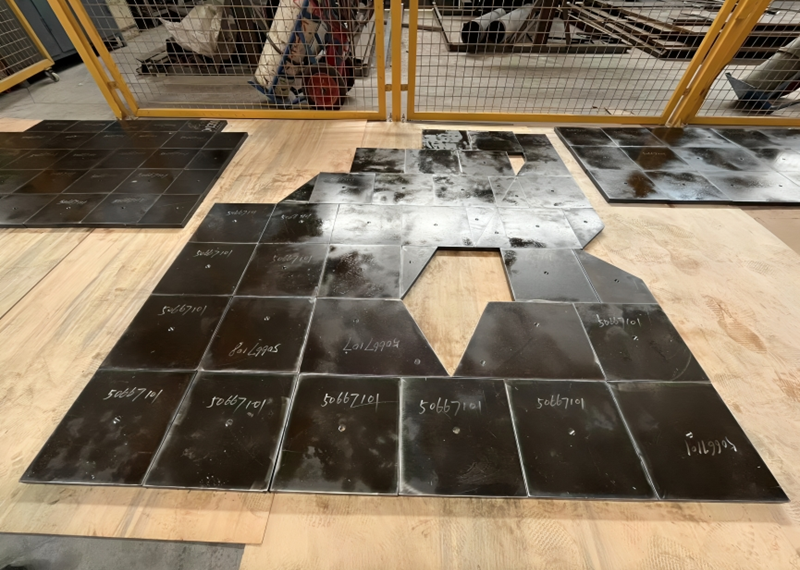
Where it is used
- Impact crusher chambers
- Protection of exposed internal surfaces
What we need for a quote
- Machine model and position diagram
- Drawing with hole centres and thickness
- Impact conditions and observed wear
Specify the component
| Selection point | Information to provide |
|---|---|
| Liner position and orientation | Crusher model, part number and an annotated chamber diagram; mark the plate location, left/right side where relevant and the working face |
| New-part thickness and profile | Drawing revision, overall dimensions, original thickness and working profile; identify any stepped edges, overlaps or recesses |
| Fixing geometry and seating | Hole centres, hole or thread sizes, bolt-head seating and access from each side; include the mounting face and adjacent-part clearances |
| Feed and operating duty | Processed material, feed-size range and largest pieces, contamination or tramp-material risk and the present operating arrangement |
| Wear evidence and replacement scope | Photographs of the wear pattern and mounting face, current material reference if known, quantity per position and whether fasteners are included in the enquiry |
Send a drawing revision or part reference, the quantity for each item and your delivery destination. Material grade, tolerances, inspection records and delivery terms are agreed in the quotation; they are not assumed from the product name.
Selection guidance
Identify the installed position before selecting a material
Breaker-plate liners, side liners and rotor-mounted blow bars do different jobs. Start with a marked chamber diagram and the reference for each plate being replaced. For rotor-mounted parts, use the impact crusher blow bar guide instead of treating every wear component as a chamber liner.
Record the fitting geometry as well as the worn surface
A worn plate alone can hide its original thickness, edge profile and fixing details. Send the current drawing revision with photographs of the working and mounting faces, using records from planned, isolated maintenance. Describe where wear, cracking or loosening occurred. The application and fastening arrangement must be reviewed together before a replacement material or profile is agreed.
Can all chamber liners use one material?
Different positions experience different loads. Impact zones and sliding-wear zones may require different material specifications.
How is compatibility confirmed?
We compare the equipment reference, drawing, fixing geometry and operating conditions. Manufacturer and model names identify the intended application; they do not establish OEM supply or an affiliation.
Related products
Jaw Crusher Plates & Cheek Plates
Fixed and moving jaws, cheek plates and associated wear surfaces for jaw crushers. Tooth profile and fitting geometry are defined against the crusher and feed.
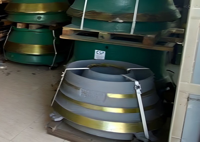
Cone Crusher Mantles
Moving wear liners for cone crushers. The mantle profile is selected as part of the crushing chamber, together with the matching bowl liner.
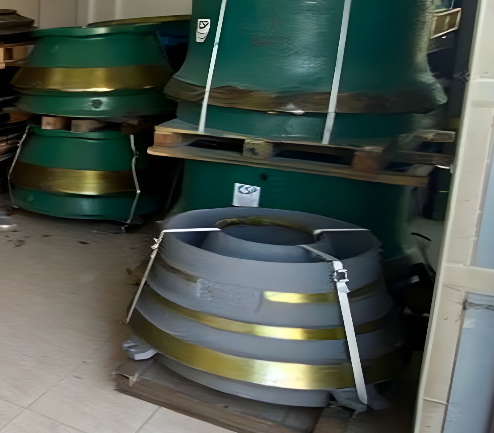
Cone Crusher Bowl Liners
Stationary cone crusher liners for the specified chamber configuration. Correct seating, profile and pairing with the mantle are essential identification points.